今天小编要和大家分享的是电脑主板相关信息,接下来我将从电脑主板PCI槽转正负12V、5V、5A电流输出的电路,电脑,主板,照片,棚拍这几个方面来介绍。

电脑主板相关技术文章电脑主板PCI槽转正负12V、5V、5A电流输出的电路
电脑主板PCI槽转正负12V、5V、5A电流输出的电路
Figure 1 shows a typical application using the LTC1421.The LTC1421 works best with a staggered, 3-level connector.Ground makes connection first to discharge any staticbuild-up. VCC, VDD and VEE make connection second andthe data bus and all other pins last. The connection sensepins CON1 and CON2 are located on opposite ends of theconnector to allow the board to be rocked back and forthduring insertion.
,LTC and LT are registered trademarks of Linear Technology Corporation.
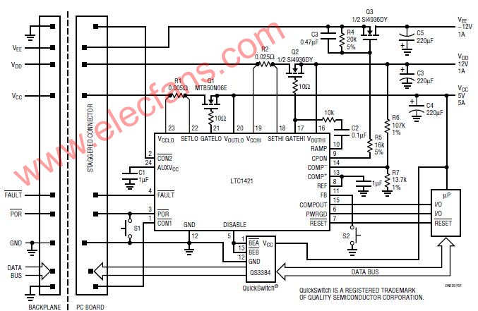
The power supplies on the board are controlled by placingexternal N-channel pass transistors Q1, Q2 and Q3 in thepower path for VCC, VDD and VEE, where VCC and VDD canrange from 3V to 12V, and VEE from – 5V to – 12V. Byramping up the voltage on the pass transistors’ gates at acontrolled rate, the transient surge current [I = (C)(dv/dt)]drawn from the main backplane supply will be limited to asafe value. The ramp rate is set by the value of capacitor C2.The board’s data bus is buffered by a QS3384 QuickSwitchfrom Quality Semiconductor. Disabling the QuickSwitchvia the DISABLE pin during board insertion and removalprevents corruption of the system data bus.Resistors R1 and R2 form an electronic circuit breakerfunction that protects against excessive supply current.When the voltage across the sense resistor is greater than50mV for more than 20ms, the circuit breaker trips, immediatelyturning off Q1 and Q2 while the FAULT pin is pulledlow. The device will remain in the tripped state until the PORpin is pulsed low or the power on VCCLO and VCCHI is cycled.The circuit breaker can be defeated by shorting VCCLO toSETLO and VCCHI to SETHI.The RESET signal is used to reset the system microcontroller.When the voltage on the VOUTLO pin rises abovethe reset threshold, PWRGD immediately goes high andRESET goes high 200ms later. When the VOUTLO supplyvoltage drops below the reset threshold, PWRGD immediatelygoes low, and RESET goes low 60ms later, allowingthe PWRGD signal to be used as an early warning that areset is about to occur. When the FB is left floating, the resetthreshold is 4.65V; when the FB pin is tied to VOUTLO, thereset threshold is 2.90V.The uncommitted comparator and internal voltage reference,along with resistors R6 and R7, are used to monitorthe 12V supply. When the supply drops below 10.8V, theCOMPOUT pin will go low. The comparator can be used tomonitor any voltage in the system.Push-button switches S1 and S2 are used to generate ahard and soft reset, respectively. A hard or soft reset mayalso be initiated by a logic signal from the backplane.Pushing S1 shorts the POR pin to ground, generating ahard reset that cycles the board’s power. Pass transistorsQ1 to Q3 are turned off and VOUTLO and VOUTHI are activelypulled to ground. When VOUTLO discharges to within 100mVof ground, the LTC1421 is reset and a normal power-upsequence is started.Pushing S2 shorts the FB pin to ground, generating a softreset that doesn’t cycle the board’s power. PWRGD immediatelygoes low, followed 64ms later by RESET. When S2 is released, PWRGD immediately goes high, followed 200mslater by RESET.Board Insertion TimingWhen the board is inserted, GND pin makes contact first,followed by VCCHI and VCCLO (Figure 2, time point 1).DISABLE is immediately pulled high, so the data bus switchis disabled. At the same time CON1 and CON2 make contactand are shorted to ground on the host side (time point 3).When CON1 and CON2 are both forced to ground for morethan 20ms, the LTC1421 assumes that the board is fullyconnected to the host and power-up can begin. WhenVCCLO and VCCHI exceed the 2.45V undervoltage lockoutthreshold, the 20mA current reference is connected fromRAMP to GND, the charge pumps are turned on and CPONis forced high (time point 4). VOUTHI and VOUTLO begin toramp up. When VOUTLO exceeds the reset threshold voltage,PWRGD will immediately be forced high (time point5). After a 200ms delay, RESET will be pulled high andDISABLE will be pulled low, enabling the data bus (time point 6).
关于电脑主板就介绍完了,您有什么想法可以联系小编。